Oscar Amaya
In this series of short technical articles, we look at various topics that illustrate the complexity of renewables as a concept within the ongoing energy transition. In this article, PSC’s Oscar Amaya writes about building dynamic network equivalent models to reduce the complexity of studying the potential impact of renewables on the full-scale power system.
Dynamic Network Equivalents
In recent years, integrating renewable generation technologies has become a focal point of interconnected electricity systems. Grid interconnection studies are performed in the full-scale power system to assess the impact of renewable projects on the electrical grid. These studies can sometimes be complex and challenging, specifically if the need is to perform dynamic (RMS) or electromagnetic transient (EMT) simulations. Therefore, dynamic network equivalents present an attractive option to reduce the complexity and simulation times while maintaining high accuracy in the model.
As a basic definition, power system network equivalents represent the original electrical system at a reduced scale. Therefore, network equivalents enable us to look at a specific area of interest within a network while maintaining the system’s original behavior. Depending on the type of study to be performed, a degree of sophistication will be imposed on the reduced network, thus adding a layer of complexity.
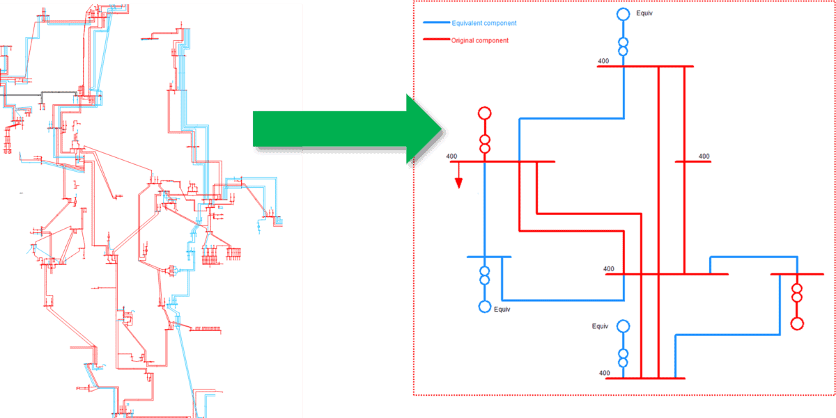
For example, a network equivalent intended to be used for steady state analysis – such as load flow and short circuit calculations – would require a different degree of complexity than a network equivalent used in dynamic simulations. The level of detail of a dynamic network equivalent will also vary according to the type of dynamic study to be performed, such as electromagnetic transients, transient stability, and so on. Figure 1 shows an example of the AC equivalent representation.

Figure 1: Example of an AC equivalent representation. The network to the right illustrates the reduced network: red elements indicate the retained components and blue elements indicate the equivalent network.
Meeting a number of needs
There are many different reasons for using network equivalents.
For instance, the limited size and capacity of tools used in studies such as EMT-type programs (e.g. PSCAD) mean that a network equivalent is the most appropriate approach.
In Factory Acceptance Tests (FATs) of control devices, network equivalents enable the FATs to be performed in real-time simulators (such as RTDS and OPAL-RT).
Network equivalents are also useful to significantly cut computation times or in projects where the original network is confidential and cannot be published.
Creating a network equivalent
Different types of network equivalents and the type of analysis to be performed are choices that impose a degree of complexity on the reduced network. A steady state analysis, for example, is associated with a low degree of complexity. However, in dynamic analysis, the degree of complexity is much higher.
In general, to create a network equivalent, the original network is partitioned into three parts:
- The subsystem that needs to be retained, along with its original structure and data
- The subsystem that needs to be reduced
- And, finally, the coupling lines that need to be retained between both subsystems.
The first stage in creating the network equivalent is to combine the original generators in the subsystem into groups of equivalent generators. A high degree of reduction implies that only a limited number of network contingencies will closely agree with results from the original system.
In the reduction stage that follows, the original generator nodes are removed from the original system.
Each equivalent generator should now perform similarly to the original generator in terms of voltage, frequency, and power oscillations. Determining the correct equivalent impedance ensures that the equivalent machines’ subtransient, transient, and steady state behavior is comparable to the behavior of the original generators.
During the reduction of the passive network, buses that are neither equivalent generator buses nor buses that need to be kept are eliminated.
Different generator controls – such as automatic voltage regulators (AVR), governors, power system stabilizer (PSS) and their settings – will considerably influence the system’s dynamic behavior. So, they need to be reflected in the generators within the network equivalent.
Different types and methods
While there are several methods, the two classical choices are the Ward Equivalent and the Radial Equivalent-Independent (REI) model.
The Ward Equivalent approach forms a linear part-representation by admittances between retained nodes. A non-linear part comprises constant current injections in the nodes that correspond to points of generation and load.
With REI, the main characteristic is the grouping of a set of nodes in a common node. This means there can be different REI nodes for both load and generation.
Validation and accuracy
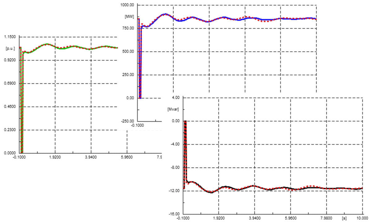
To validate the accuracy of the derived network equivalent, simulations on test events have to be performed and compared in both the original and reduced network. Figure 2 compares results between a reduced network (blue, green or black trace) and the original network (dashed red trace), highlighting the system response (voltage, current and power) to a three-phase fault that is applied at 1 second and cleared after a few cycles.

Figure 2: Results comparison between original and equivalent network
Conclusions
When implementing network equivalents, the main challenge is to account for the dynamic response of the network, where several criteria are applied, including:
- Generators in the subsystem to be reduced are combined into groups of coherent generators. In other words, generators are grouped based on their tendency to swing together after a disturbance.
- Generator controllers are then selected and adjusted to match the dynamic response of the pre-reduction system (original).
Depending on the application of the network equivalent, it could be further limited where a real-time simulator is used. This is because the size of the network may be restricted by the real-time simulator’s capability compared to the typical dynamic network equivalents used for power system studies. Other real-time simulator restrictions – such as element component definitions (negative loads, line time constants, etc.) – may also pose additional challenges.
If you’re looking for help with your power system studies, here’s more information about our capabilities. Please contact us to get started!
Series links
The complexity of renewables, Part 1 – PSC Consulting
The complexity of renewables, Part 2 – PSC Consulting
The complexity of renewables, Part 3 – PSC Consulting
The complexity of renewables, Part 4 – PSC Consulting
The complexity of renewables, Part 5 – PSC Consulting
The complexity of renewables, Part 6 – PSC Consulting
The complexity of renewables, Part 7 – PSC Consulting
The complexity of renewables, Part 8 – PSC Consulting
The complexity of renewables, Part 9 – PSC Consulting
