Zia Emin
In this series of short technical articles, we look at various topics that illustrate the complexity of renewables as a concept within the ongoing energy transition. Here, PSC’s Zia Emin discusses the potential impacts of renewable energy on power quality.
Power Quality – Harmonics
Problem Definition
In broad terms, power quality is defined as the degree to which the voltage, frequency and waveform of a power supply system conform with respect to established criteria. There are many sub-categories within power quality such as harmonic distortion, unbalance, voltage dip and so on.
A key consideration with inverter-based resources is the heavy utilization of power electronics and hence the generation of harmonics. Harmonics are integer multiples of the fundamental frequency, so if your frequency is 50 Hz then the 2nd harmonic is at 100 Hz, 3rd at 150 Hz, etc.
Harmonics can present a two-fold issue with regard to power systems. At one end there is the possibility of exciting harmonic resonance during certain switching events such as transformer energization where the inrush current associated with the energization is rich in harmonic content. However, this harmonic content varies with time in a decreasing fashion. There is always the possibility that an energization event of such transformers can excite an existing resonance and create temporary overvoltages. This is a voltage that is added on top of the fundamental frequency voltage and has the tendency to cause damage to various equipment (surge arresters being one of them if not rated properly). This type of harmonic issue is temporary in its nature and is observed only during certain events.
The second type of harmonic issue relates to permanent harmonic distortion in the voltage waveform. This is primarily caused by harmonic emissions from power electronic equipment due to switching and/or nonlinear loads drawing distorted waveforms with harmonic content. The result is a voltage drop proportional to system impedance (impedance of the system at that frequency) and the observation or presentation of this distorted voltage to other system users.
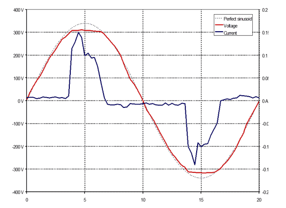
Figure 1 shows a typical current drawn by a PC powered by main voltage and the associated voltage observed at the point the equipment is powered. The voltage drop impressed on the fundamental voltage waveform is clearly visible.

Figure 1 v(t) & i(t) of a PC power supply [1]
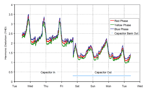
The issue at hand here is normally referred to as the amplification of background harmonics. It is important to note that developments without active harmonic emission components may also be amplifying existing harmonics on the system due to their impedance characteristics and therefore are subjected to similar restrictions in terms of harmonic compliance. Figure 2 shows the effect of shunt capacitor switching on harmonic levels.

Figure 2 Effect of capacitor switching on measured harmonics [1]
Possible Effects of Harmonics
The presence of such permanent harmonic distortion in the system creates a few challenges. The main issue is that this harmonic distortion has an associated energy that is dissipated in the form of heating in various plants such as cables, transformers, capacitor banks, etc. Figure 3 shows a damaged capacitor bank.
The second issue is that the presence of harmonics is not good for protection devices or high-accuracy meters, they can cause misoperation.

Figure 3 When thing go wrong- exploded capacitor bank [1]
Assessment Approach
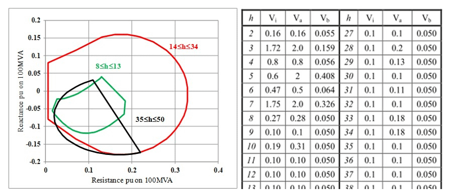
System owners/operators are therefore keeping a close eye on the level of harmonics present in their systems. The most common way of approaching this involves considerable work at the system development stage. During the application to connect process, transmission or distribution system owners perform elaborate and complicated system studies in order to establish the level of headroom in their system in terms of harmonics and how much harmonic distortion they can accommodate from the specific customer. This is normally referred to as emission limits specific to that connection. Development of emission limits involves extensive modeling and analysis and along with the emission limits, utilities normally establish their system impedance characteristics to pass along to the connecting customer. This is usually in the form of system impedance loci and can be in multiple numbers, each representing a single harmonic order or a range of harmonics.
There is no clear-cut rule, however, most experienced utilities would tend to produce loci in ranges of harmonics in order to cater to uncertainty with modeling and data. Unfortunately, it is still possible to see a lack of such information in some cases, and in such cases, the provision of short circuit impedance is the first port of call. This is the impedance of the system at the fundamental frequency with the expectation that t can be adjusted for increasing frequency. This is not a recommended practice and system short circuit impedance can only be used up to the first resonance point and beyond that it fails to represent the system characteristics.

Figure 4 Typical system impedance loci and emission limit (both incremental and aggregate limits are shown along with existing background information) for an offshore wind development [2]
Mitigation Approach
In the case of a breach of limits, some form of mitigation measure will be required in order to demonstrate compliance back to the utility. The most common form of such mitigation is the introduction of passive shunt harmonic filters. These come in different shapes and forms (such as single-tuned, double-tuned, high-pass, or c-type filters). In essence, filters provide a low impedance path for specified frequencies (one frequency in the case of a single tuned and so on) and alter the system’s response for that specific frequency.
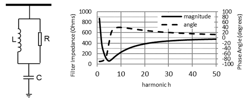
High-pass or c-type filters would normally work for a range of frequencies (highly effective at the tuned frequency but also provide some support beyond the tuned frequency). A high-pass filter of 20Mvar tuned to the 5th harmonic for the typical example case study is shown in Figure 5.
The design of such mitigation measures requires the assessment studies to be repeated to demonstrate compliance under all given conditions. In European countries, one should expect to see a desktop analysis report being presented back to the utility showcasing compliance with their development from the customer side.

Figure 5 Mitigation and its characteristics employed for the typical example case [2]
The measurements are continued following energization (i.e. With the new connection connected to the system and operating). A simple comparison of pre- and post-connection measurement, in this case, provides a good indication of compliance verification. It is a given that this simple comparison cannot create and is not demonstrative of all the conditions examined during the assessment period but it at least provides some form of confidence for the given conditions when establishing the incremental effect of the new condition.
It is also common to encounter continuous monitoring following such developments by some utilities. This provides a permanent base to measure and monitor harmonic distortion on the system with the ability to see increasing or decreasing trends in the system in general and also any peculiar changes following switching events.
Conclusions
Harmonics are introduced into the power system by employing a high degree of power electronics in inverter-based resources. Analytical approaches are used to assess impacts and available mitigation measures can be successfully introduced.
References
[1] Z Emin, “Assessment of Harmonic Distortion and Voltage Unbalance”, IEE Seminar on Power – It’s a Quality Thing, 16 February 2005, Savoy Place, London, United Kingdom
[2] Z Emin, F Fernandez, M Poeller and G E Williamson “Harmonic Distortion Specification and Compliance of an Offshore Wind Generation” Paper 0054, IET ACDC2012 Conference
Series links
The complexity of renewables, Part 1 – PSC Consulting
The complexity of renewables, Part 2 – PSC Consulting
The complexity of renewables, Part 3 – PSC Consulting
The complexity of renewables, Part 4 – PSC Consulting
The complexity of renewables, Part 5 – PSC Consulting
The complexity of renewables, Part 6 – PSC Consulting
The complexity of renewables, Part 7 – PSC Consulting
The complexity of renewables, Part 8 – PSC Consulting
The complexity of renewables, Part 9 – PSC Consulting
