
Hesam Marzooghi & Djino Pirsic
This is the second article in a two-part series aimed at highlighting the role of Battery Energy Storage Systems (BESS) in future power systems. In the first article (The role of BESS in future power systems–Part1 [1]), authors Djino Pirsic and Hesam Marzooghi addressed decarbonization as a driver of BESS development, discussed recent technological developments and touched on the fact that these technologies can provide the inertia needed for grid stability. In this follow-up article – with additional collaboration from Mohammad Seidali and Amir Mehrtash – the authors focus on grid-forming inverters, looking at the various types, their limitations, and the services they can provide.
Grid-forming BESS: opportunities and challenges
As mentioned in our earlier article, The role of BESS in future power systems–Part1 [1], the make-up and operation of power systems – whether at a grid level or for smaller islanded systems – is becoming more complex with the increasing penetration of diverse intermittent renewable inverter-based resources (IBR). The intermittency of such resources has made balancing IBRs, conventional generation and load challenging. For stable and reliable power system operation, the amount of active power generation must always equal the amount of consumption and losses, which must be balanced in real-time. To compensate for the inherent variability in output power of IBR generation, BESS can be utilized to offset the imbalance by providing power during low outputs and absorbing power during high outputs.
With higher penetration of IBR renewable generation, balancing in power systems is not the only concern. It is expected that with higher penetration of IBR renewables combined with progressive decommissioning of fossil-fuelled Synchronous Generators (SGs), power system dynamics will change in unconventional ways. This is mainly because IBR generation is connected to the grid via power electronics interfaces with different characteristics and limitations than SGs. Many studies, and the experience of network operators, are showing that the increasing integration of IBRs is displacing system strength and inertia in the power systems that SGs have historically provided. It is expected that increasing the number of BESS applications using grid-forming (GFM) technology inverters to address system strength and inertia shortcomings developing in power systems will enable higher penetration of IBR renewable generation and less dependence on fossil-fuelled SGs.
Grid-following and grid-forming inverters
Most inverters currently installed for IBR renewable generation are of the grid-following (GFL) type (although GFM inverters may become more common). They are commonly referred to as current source inverters (CSI), which require, by design, other generators in the network (usually SGs) to provide grid voltage and frequency reference for synchronization. The majority of GFL inverter control methods were initially based on the assumption that change in IBR injected current will not move the voltage and frequency in the network tangibly (i.e., there is a strong or stiff network to which IBRs will be connected to).
On the other hand, GFM inverters (commonly referred to as voltage source inverters) are a class of inverters that can provide their own frequency and voltage references and regulate their output voltage. This is essentially equivalent to grid-connected SGs with some limitations, as detailed below.
Please refer to our earlier article, The role of BESS in future power systems–Part1 [1] for more details on GFM and GFL technologies.
Grid-following vs. grid-forming inverters
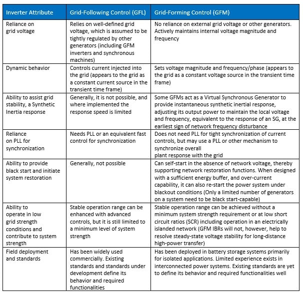
Presently, IBR renewable generation based on GFL control methodology may not be sufficient to ensure grid stability in future power systems with low system strength. GFM inverter control technology has been considered as a potential solution in recent years. This is mainly due to the features only provided by GFM, compared to GFL, which does not offer the same characteristics (or provide them in a limited manner), as summarised in Table 1.

Table 1: Features of grid-following Vs. grid-forming inverters- adopted from [2], and modified.
Pilot grid-forming projects
The study in [3] summarized some of the major GFM pilot projects in the world. In future power systems, GFM inverters will be increasingly important in network stability and IBR renewable expansion to support decarbonization.
Apart from the pilot projects mentioned in [3], which are built and operational, many others are planned for future power systems, particularly in Australia. Those projects have been approved, are in the pipeline, or are in construction, providing virtual inertia or grid strengthening services. Here are some examples:
- A 50 MW / 100 MWh GFM BESS in Broken Hill, New South Wales
- A 250 MW/250 MWh GFM BESS in Torrens Island, South Australia
- A 125MW GFM BESS to be built in the Murray Renewable Energy Zone (REZ), Victoria
- Koorangie Energy Storage System (KESS) in Victoria to increase the renewable hosting capacity of the Murray River REZ by up to 300MW through the provision of system strength to improve network stability.
Australian Renewable Energy Agency (ARENA) backs eight big BESS to bolster the grid. Eight of the largest batteries ever built in Australia will boost grid-forming storage capacity tenfold. They are as follows [4]:
- AGL: a new 250 MW / 500 MWh battery in Liddell, NSW.
- FRV: a new 250 MW / 550 MWh battery in Gnarwarre, VIC.
- Neoen: retrofitting the 300 MW / 450 MWh Victorian Big Battery in Moorabool, VIC to enable grid- forming capability.
- Neoen: a new 200 MW / 400 MWh battery in the Western Downs, QLD.
- Neoen: a new 200 MW / 400 MWh battery in Blyth, SA.
- Origin: a new 300 MW / 900 MWh battery in Mortlake, VIC
- Risen: a new 200 MW / 400 MWh battery in Bungama, SA.
- TagEnergy: a new 300 MW / 600 MWh battery in Mount Fox QLD.
Grid-forming inverter types
There are various types of GFM inverters proposed in the literature [5] [6] [7] [8] [9] , summarised in Figure 1. Virtual Synchronous machines (VSM) and droop-based technologies are the main GFM commercialized and used in power systems nowadays. Apart from those shown in Figure 1, other GFM control approaches are being developed such as power synchronization control (PSC) and synchronverter [3]. The high-level control mechanism behind these GFM inverters is summarised below:
- Droop control: “It is the simplest GFM implementation, where the internal frequency is determined by multiplying the difference between the active power reference and the measured active power by a gain, and then obtaining the converter angle integrating the synthesized frequency signal” [3].
- Power synchronization control (PSC): “It is a GFM method similar to droop controls, where the converter angle variation is determined by integrating the difference between the reference and the measured active power multiplied by a gain, and then the converter angle is obtained by adding the integral of a reference frequency to the angle variation determined by the power-angle control” [3].
- Synchronverter and VSM: “They are GFM schemes which realize the GFM capabilities by a direct emulation of the characteristics of SGs, simply replicating the intrinsic behavior defined by the swing equation or implementing more complex control schemes to include the replication of the machine electrical dynamics” [3].
- Matching control: “In the GFM, the converter pulse-width-modulation signal is controlled to achieve exact matching between the converter in closed-loop and the SG dynamics, while direct power control technique is based on p-q theory and instantaneous power errors of active and reactive power components are kept within a fixed hysteresis band to provide reference values of powers” [3].

Figure 1: Several GFM inverter controls from the literature, adapted from [10] ©2021 EPRI, used with permission.
It is worth mentioning that there is a lack of synthetic inertia with the droop control GFM, which can lead to a large frequency deviation and a high rate of change of frequency (RoCoF) when operating with existing SGs. To address this issue, the concept of VSM was proposed by introducing an inertia-emulating term into the basic droop control, as discussed in [11].
While each of the GFM control mechanisms in Figure 1 has their own advantages (especially when compared to GFL inverters), they are prone to small-signal and transient stability phenomena, which can impact the stable and secure operation of future power systems [11]. These challenges are briefly summarized in the next section and necessitate careful GFM technology selection and tuning for different applications.
Grid-forming inverter limitations and challenges
While benefiting from the SG-like features, GFM inverters are prone to suffer from stability problems during grid disturbances. Consequently, substantial research efforts have been devoted to this issue, focusing mainly on small-signal and transient stability as discussed in [11].
It is discussed extensively in [11], that the PSC and the basic droop control GFM can retain a stable operation as long as there are equilibrium points (stable operating conditions), due to their non-inertial transient responses. Conversely, the droop control with low-pass filters (LPFs) and the VSM control GFM can be destabilized even if the equilibrium points exist, due to the lack of damping on their inertial transient responses, as detailed in [11]. This is because the inertial GFM control schemes, i.e., the droop control with LPFs and the VSM control, are a second-order system, hence have dramatically different transient behaviors compared with the non-inertial ones. The overshoot in the response of such control approaches (i.e., second-order system) is shown in Figure 2-(b), where this can be reduced by tuning parameters. Further, it is demonstrated in [11] that there is a conflict between the frequency and transient stability in terms of the virtual inertia for VSM control GFM technologies. This necessitates careful tuning inertia and damping to ensure both frequency and transient stability criteria can be provided with VSM control GFM inverters.
The last point to note here is that these discussions are based on assuming GFMs do not hit their current limits (maximum safe inverter output current) during stability phenomena. If the maximum current limit of the inverter is reached, the performance of GFM can further deteriorate. Researchers are working on enhancing the control mechanisms to address the shortcomings [11].

Figure 2: Transient stability of (a) non-Inertial grid-forming control (e.g. PSC and basic droop control), and (b) Inertial grid-forming control- An LPF in both active and reactive loop [11] © 2019 IEEE, used with permission.
Other services an advanced BESS can provide
Many network operators globally are experiencing ever greater penetration of IBRs as energy generation transitions to sustainable energy sources. As the reliance on conventional SG declines, this leads to significant transformations and developments in generating technology and where it is located. The vast majority of IBR is at this time connected through GFL inverters, but this will also need to change to overcome new challenges in maintaining network stability and security, which we have come to expect.
The historical reliance on carbon-fuelled SGs for network stability will need to be replaced by a similar dependence on advanced GFM inverter BESS installations which will continue to improve in their capabilities, cost and constructability.
At PSC, our engineers support clients from all sectors of the energy sector to enable them to execute their energy decarbonization strategies, maintain network security and assist with the compliance and connection process for advanced IBRs.
The section below identifies the main services where BESS technology provides benefits for energy generators and network operators. Developers of BESS projects do not rely on just one capability as that may limit the optimum utilization of the batteries and inverter hardware and may not be economically viable. It is common for developers to maximize value by appropriately selecting and sizing BESS and inverter technology and value-stacking multiple services that the BESS and inverters can provide to the network.
Arbitrage:
Definition: Purchasing low-cost off-peak energy and selling it during periods of high prices.
Applications:
- Reducing renewable energy curtailment (which often occurs when there is an excess of renewable energy generation capacity that cannot be consumed or stored).
- Load-leveling (storing energy during low demand and delivering it during high demand).
Firm Capacity or Peaking Capacity:
Definition: Provide reliable capacity to meet peak system demand.
Applications:
- To reliably meet demand during the highest-demand periods in a given year or the peak demand. Peaking generation capacity.
- Pairing renewable IBR resources with BESS to coincide with peak demand.
- GFM inverter BESS has been successfully used to replace hydrocarbon-fuelled gas turbines and diesel power generators employed for spinning reserve or peaking capacity.
- BESS can provide fault ride-ride through capability in hybrid generation systems where there is the likelihood of spinning machine failure or delay in machine re-start time.
Operating Reserves and Ancillary Services:
Including:
- Primary frequency response
- Synthetic inertia or virtual synchronous generator response
- Voltage and power factor regulation
- Contingency spinning reserve
- Replacement/supplemental
- Ramping/load following
Applications:
- To ensure grid stability and reliability.
- BESS can rapidly charge or discharge in a fraction of a second, faster than conventional thermal plants.
- Short-term reliability services such as Primary Frequency Response (PFR) and Regulation.
- Longer-duration services, such as load-following and ramping services to ensure supply meets demand.
Transmission and Distribution Upgrade Deferrals:
Definition: Reduce peak loading on transmission and distribution systems.
Applications:
- Deferral of expensive distribution infrastructure upgrade costs such as those that occur with transformers and conductors (even extending to generator augmentation).
- Better utilization of transmission and distribution infrastructure which must be sized to meet peak demand which may only occur over a few hours of the year.
- Mobile BESS installations can be relocated to new areas when no longer needed in the original location.
Black Start:
Definition: Generation brought online to start a system after a system-wide failure (blackout).
- Appropriate generators must be started through an on-site source of electricity, such as a diesel generator.
- Not all forms of generation are suitable for black start application. GFM inverter BESS are capable of supporting black start services.
- An on-site BESS can also provide this service, avoiding fuel costs and emissions from conventional black-start generators
References
| [1] | a. H. M. Djino Pirsic, “The role of BESS in future power systems–Part 1,” Energy Source & Distribution, Sep-Oct 2022. |
| [2] | H. S. o. I.-B. G. T. F. 2022., “Grid-Forming Technology in Energy Systems Integration,” Reston, VA: Energy Systems Integration Group, EGIS, 2022. |
| [3] | R. Musca, A. Vasile and G. Zizzo, “Grid-forming converters. A critical review of pilot projects and demonstrators,” Renewable and Sustainable Energy Reviews, vol. 165, 2022. |
| [4] | ARENA, 17 December 2022. [Online]. Available: https://arena.gov.au/news/arena-backs-eight-grid-scale-batteries-worth-2-7-billion/. |
| [5] | J. Liu, Y. Miura, H. Bevrani and T. Ise, “Enhanced Virtual Synchronous Generator Control for Parallel Inverters in Microgrids,” EEE Transactions on Smart Grid, vol. 8, no. 5, pp. 2268-2277, 2017. |
| [6] | C. Arghir and F. Dörfler, “The Electronic Realization of Synchronous Machines: Model Matching, Angle Tracking, and Energy Shaping Techniques,” IEEE Transactions on Power Electronics, vol. 35, no. 5, pp. 4398-4410, 2020. |
| [7] | J. Liu, Y. Miura and T. Ise, “Comparison of Dynamic Characteristics Between Virtual Synchronous Generator and Droop Control in Inverter-Based,” IEEE Transactions on Power Electronics, vol. 31, no. 5, pp. 3600-3611, 2016. |
| [8] | D. Ramasubramanian, W. Baker and E. Farantatos, “Operation of an All Inverter Bulk Power System with Conventional Grid Following Controls,” CIGRE Science & Engineering, vol. 18, pp. 62-76, 2020. |
| [9] | G. Seo, M. Colombino, I. Subotic, B. Johnson, D. Groß and F. Dörfler, “Dispatchable Virtual Oscillator Control for Decentralized Inverter-dominated Power Systems: Analysis and Experiments,” in IEEE Applied Power Electronics Conference and Exposition (APEC), Anaheim, CA, USA, 2019. |
| [10] | EPRI, “Grid Forming Inverters: EPRI Tutorial. EPRI,” Palo Alto, CA: 2021. 3002021722, 2021. |
| [11] | D. Pan, X. Wang, F. Liu and R. Shi, “Transient Stability of Voltage-Source Converters with Grid-Forming Control: A Design-Oriented Study,” IEEE Journal of Emerging and Selected Topics in Power Electronics, vol. 8, no. 2, pp. 1019 – 1033, 2020. |
The role of BESS in future power systems–Part 1 – PSC Consulting
