

Data centers are now among the fastest growing and most complex loads on the grid. Unlike traditional industrial loads, these sites don’t draw power in predictable ways; their power draw is dominated by electronics, massive banks of servers fed through uninterruptible power supply (UPS) systems, and advanced cooling equipment that can ramp up sharply without warning.
Keeping both the grid and the data center stable means understanding how all these moving parts behave. That’s why engineers now rely on detailed PSCAD and PSSE models to see how these sites really behave during everyday operation and system disturbances. PSC helps make sense of it all, turning complex modeling into clear guidance that supports better planning and reliable interconnections.
Existing ISO Large Load Constructs
Data centers are now a major driver of changes in how ISOs and utilities across North America handle large load interconnections. As these facilities grow in size and number, system operators are updating definitions, thresholds, and study requirements to keep pace.
Before September 2025, ERCOT and New York ISO (NYISO) were the only US Independent System Operators (ISOs) to have requirements for large-load interconnection. In 2022, NERC made modifications to its requirements and measures for facility interconnection studies (FAC-002-4), but it didn’t have any MW threshold or special process for large loads.
To stay ahead of the rapid growth, ERCOT established an interim large‑load interconnection process in 2022. This required transmission service providers to submit interconnection studies that meet the NERC Reliability Standard FAC-002-2 requirements for large loads seeking to connect within two years.
ERCOT then formalized and improved this process on April 15, 2025 through NPRR1234 and PGRR115. These updates:
- Redefined large load as one or more facilities at a single site with ≥75 MW of peak demand behind common Points of Interconnection (POIs) or Service Delivery Points
- Formalized interconnection and modeling standards for large loads (≥75 MW), set standards for loads ≥25 MW
- Set reactive power study requirements for sites adding ≥20 MW of load alongside existing generation.
- Established a standardized Large Load Interconnection Study (LLIS), performed by the transmission service provider (TSP) and reviewed by ERCOT.
These changes reflect a broader industry trend: as data center growth continues, system operators are tightening requirements to ensure grid reliability and consistent interconnection outcomes.
As shown in the figure, ERCOT experiences the most significant and volatile growth in large-load additions over the 2025–2031 period, driven primarily by data center development. Data center demand increases from near zero in 2025 to approximately 24 GW by 2031, representing the dominant contributor to total load growth. This rapid escalation highlights the increasing grid impacts and the strong regional concentration of hyperscale and AI driven infrastructure, underscoring the need for proactive planning and interconnection strategies.

Figure: ERCOT Adjusted Large Load Breakdown [1]
Key Modeling and Study Considerations
Accurately representing data center behavior requires models that capture fast transients, electronic power conversion, and complex control interactions, far beyond what traditional industrial load models provide.
This includes:
- Operational switching: Switching events such as bypassing the UPS module, engaging backup generators, and energizing capacitor banks produce fast transients. High fidelity EMT simulations capture these dynamics, including traveling waves and nonlinear effects, which are critical for proper relay coordination and system stability.
- Power supply systems: A data center’s power architecture uses a mix of utility feeds, UPS systems, automatic transfer switches (ATS), diesel generation, and increasingly battery storage, each demanding careful modeling to reflect real-world responses.
For instance, UPS units carry the IT load across grid outages until diesel generators start via ATS. Models must include these pieces: UPS control logic, transfer switches, and generator dynamics. They may also include behind-the-meter resources such as batteries or solar that act as flexible loads or grid services. Simulating this mix ensures an accurate representation of the site’s supply behavior.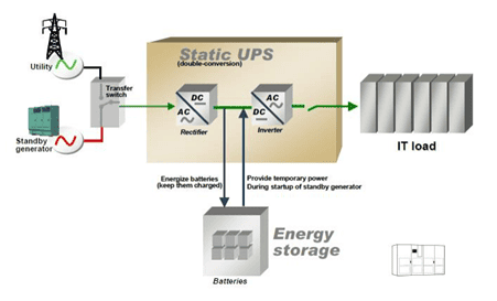
Figure 2 Static Centralized UPS | Source: Schneider Electric White Paper 92
- Ride-through performance: Data center equipment must remain operational and ride through voltage sags and swells, such as LVRT and HVRT. Modeling is essential to ensure their equipment stays online during faults.
Detailed EMT models incorporate UPS rectifier and inverter controls, as well as voltage ride-through logic. By simulating low- and high-voltage trip thresholds, engineers can verify that UPS and Power Factor Correction (PFC) systems continue to operate during faults. In practice, PSCAD models of large data center loads include customizable LVRT and HVRT blocks to study how these settings affect grid stability. - Cooling and auxiliary loads: Cooling systems, often representing up to 40% of site demand, act as dynamic motor loads with VFD-driven harmonics that significantly affect stability studies.
Cooling systems such as Computer Room Air Conditioning units (CRAC), compressors, tower pumps, and fans often constitute 10 to 40% of data center power. These loads are typically motor driven with Variable Frequency Drive (VFDs) and introduce both dynamic torque and harmonic currents.
Accurate models need to include motor inertia dynamics and VFD control. The detailed EMT simulations must include cooling systems, VFDs, and UPS units to capture oscillatory behavior. Overlooking these would miss key impacts on voltage and stability.


Figure 3 Data center cooling system schematic
- Load ramping and cycling: Data center workloads can shift in milliseconds, so load models must reflect rapid ramp rates and cycling behavior to properly assess voltage and frequency impacts.
For example, IT workloads may scale up in split seconds, and such ramping or quasi periodic cycling can stress grid frequency and voltage. Modeling must account for these profiles. Industry resources note that large data loads exhibit rapid ups and downs that strain frequency and voltage margins. Simulation models should include realistic ramp rates or load shedding schemes to assess system response under varying load scenarios. - Harmonics and filtering: Data centers generate significant harmonics from components such as UPS rectifiers, server power supplies, and VFD fans. A harmonic model of the facility details the current and voltage distortion levels under normal and contingency conditions. These models are used to size filters and verify IEEE 519 compliance.
For example, nonlinear equipment, such as UPS rectifiers, switched‑mode IT power supplies, and VFD‑driven cooling systems, can generate harmonic currents that distort voltage and must be carefully assessed. Tools like PSCAD, ETAP, and PowerFactory can simulate these emissions and help design mitigation measures, including filters and tuned reactors.
- TOV and TRV: Data centers can experience Temporary Over Voltages (TOV) and Transient Recovery Voltages (TRV) during switching events, faults, or backup generator transfer. These transients occur in milliseconds or microseconds and can stress sensitive equipment such as UPS systems, server power supplies, and motor loads.
Aggregated load models are insufficient for fast transient studies. Accurate results require detailed component level modeling, including cables, current transformers (CTs), voltage transformers (VTs), as well as stray capacitances and inductances.
- Reactive power capability: A transmission-connected data center must be designed and operated to continuously meet voltage needs. This requires the power factor and reactive power to be adjusted as load conditions change. Reactive power compensation equipment must respond in real time, ensuring the site meets voltage, power factor, and reactive power requirements under all operating conditions.
- Model fidelity and validation: The chosen models must balance detail and performance. Generic composite load models in PSSE can approximate overall behavior, but key components often need custom EMT models. Manufacturer specific EMT models incorporate detailed converters and control designs necessary for interactions with nearby inverters, subsynchronous oscillations, or precise ride through assessment. High fidelity PSCAD models are typically validated to ensure accuracy.

Figure 4 Data Center Modeling Components and Interconnection Assessments
PSC’s Role in Supporting Large‑Load and Data Center Integration
PSC helps utilities, RTOs/ISOs, and developers make sense of the fast-growing challenges around large data‑center loads. Our team delivers a structured two phase large‑load assessment designed to meet grid compliance requirements and ensure reliable, stable operation.
Phase 1: Modeling and Assessment: PSC analyzes the behavior of the data center under both normal and stressed conditions. This includes switching events, ride‑through performance, detailed supply configurations, cooling loads, rapid load ramps, and harmonic behavior. Our high fidelity EMT and stability studies highlight risks early, from voltage dips to oscillations, and inform the design of appropriate protection and mitigation measures.
Phase 2: Mitigations and Stability Considerations: The design must incorporate mitigation measures to minimize the risk of subsynchronous oscillations, harmonic distortion and stabilize the voltage and frequency at the Point of Interconnection (POI) under system disturbances. PSC identifies and recommends the right approach based on the applicable RTO/ISO operational characteristics and the results of detailed technical studies.
PSC stays up to date with current industry practices, including the application of fast response technologies such as grid forming battery (GFM BESS), supercapacitors, E-STATCOMs, and the implementation of soft start or controlled ramp-rate strategies to effectively manage and mitigate oscillatory behavior.
Conclusion
There’s no “one size fits all” approach to integrating large data‑center loads, which is why PSC tailors every model and study to the specific grid requirements at hand. Drawing on industry leading tools like PSCAD, PSSE, PSLF, and PowerFactory, we deliver compliant, optimized solutions that support reliable data‑center integration and long-term system performance. As data centers continue to reshape the power system, the need for clear, high-fidelity analysis has never been greater.
If you are attending DTECH and exploring questions related to large‑load modeling, grid stability, or interconnection requirements, we welcome the opportunity to speak with you. Come and meet the PSC team to discuss how we can support your transition from uncertainty to clear, well-informed decisions or to find out more about how PSC can support your next ERCOT-connected project, contact us for a chat.
[1] https://www.ercot.com/gridinfo/load/forecast?